GY-651 (HMC5883L + BMP085) Compass+Barometric Pressure Module with Arduino or PIC

.jpg)

Key Feature: (copy from web)
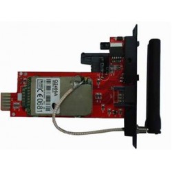
GY-651 HMC5883LBMP085MWC Four-axis Flight Control Sensor Electronic Compass Atmospheric Module
Descriptions:
- Name: electronic compass atmospheric pressure module (three-axis magnetic field + pressure)
- Model: GY-651
- The use of chip: HMC5883L + BMP085
- Power supply :3-5v (internal low dropout regulator)
- Size: 13.5mm * 15.8mm (standard pitch 2.54mm)
- Communication modes: standard IIC communication protocol)
- Magnetic field range: ± 1.3 to ± 8.1 gauss
- Pressure Range :300-1100hPa
- Chip 12bit AD converter, 16-bit data output
- Machine welding process to ensure quality
Code:
Barometric Pressure
//From Datasheet and Website http://interactive-matter.eu/blog/2009/12/05/arduino-barometric-pressure-sensor-bmp085/
//Syed Razwanul Haque(Nabil)
//Dept of Physics,SUST
//www.fb.com/Nabilphysics
//Bangladesh
#include <Wire.h>
#define I2C_ADDRESS 0x77 //77?
const unsigned char oversampling_setting = 3; //oversamplig for measurement
const unsigned char pressure_waittime[4] = { 5, 8, 14, 26 };
//just taken from the BMP085 datasheet
int ac1;
int ac2;
int ac3;
unsigned int ac4;
unsigned int ac5;
unsigned int ac6;
int b1;
int b2;
int mb;
int mc;
int md;
void setup()
{
Serial.begin(9600); // start serial for output
Serial.println("Setting up BMP085");
Wire.begin();
bmp085_get_cal_data();
}
void bmp085_read_temperature_and_pressure(int& temperature, long& pressure);
void loop()
{
int temperature = 0;
long pressure = 0;
bmp085_read_temperature_and_pressure(&temperature,&pressure);
Serial.print(temperature,DEC);
Serial.print(" ");
Serial.print(pressure,DEC);
Serial.println();
delay(100);
}
void bmp085_read_temperature_and_pressure(int* temperature, long* pressure) {
int ut= bmp085_read_ut();
long up = bmp085_read_up();
long x1, x2, x3, b3, b5, b6, p;
unsigned long b4, b7;
//calculate the temperature
x1 = ((long)ut - ac6) * ac5 >> 15;
x2 = ((long) mc << 11) / (x1 + md);
b5 = x1 + x2;
*temperature = (b5 + 8) >> 4;
//calculate the pressure
b6 = b5 - 4000;
x1 = (b2 * (b6 * b6 >> 12)) >> 11;
x2 = ac2 * b6 >> 11;
x3 = x1 + x2;
b3 = (((int32_t) ac1 * 4 + x3)<<oversampling_setting + 2) >> 2;
x1 = ac3 * b6 >> 13;
x2 = (b1 * (b6 * b6 >> 12)) >> 16;
x3 = ((x1 + x2) + 2) >> 2;
b4 = (ac4 * (uint32_t) (x3 + 32768)) >> 15;
b7 = ((uint32_t) up - b3) * (50000 >> oversampling_setting);
p = b7 < 0x80000000 ? (b7 * 2) / b4 : (b7 / b4) * 2;
x1 = (p >> 8) * (p >> 8);
x1 = (x1 * 3038) >> 16;
x2 = (-7357 * p) >> 16;
*pressure = p + ((x1 + x2 + 3791) >> 4);
}
unsigned int bmp085_read_ut() {
write_register(0xf4,0x2e);
delay(5); //longer than 4.5 ms
return read_int_register(0xf6);
}
void bmp085_get_cal_data() {
Serial.println("Reading Calibration Data");
ac1 = read_int_register(0xAA);
Serial.print("AC1: ");
Serial.println(ac1,DEC);
ac2 = read_int_register(0xAC);
Serial.print("AC2: ");
Serial.println(ac2,DEC);
ac3 = read_int_register(0xAE);
Serial.print("AC3: ");
Serial.println(ac3,DEC);
ac4 = read_int_register(0xB0);
Serial.print("AC4: ");
Serial.println(ac4,DEC);
ac5 = read_int_register(0xB2);
Serial.print("AC5: ");
Serial.println(ac5,DEC);
ac6 = read_int_register(0xB4);
Serial.print("AC6: ");
Serial.println(ac6,DEC);
b1 = read_int_register(0xB6);
Serial.print("B1: ");
Serial.println(b1,DEC);
b2 = read_int_register(0xB8);
Serial.print("B2: ");
Serial.println(b1,DEC);
mb = read_int_register(0xBA);
Serial.print("MB: ");
Serial.println(mb,DEC);
mc = read_int_register(0xBC);
Serial.print("MC: ");
Serial.println(mc,DEC);
md = read_int_register(0xBE);
Serial.print("MD: ");
Serial.println(md,DEC);
}
long bmp085_read_up() {
write_register(0xf4,0x34+(oversampling_setting<<6));
delay(pressure_waittime[oversampling_setting]);
unsigned char msb, lsb, xlsb;
Wire.beginTransmission(I2C_ADDRESS);
Wire.send(0xf6); // register to read
Wire.endTransmission();
Wire.requestFrom(I2C_ADDRESS, 3); // read a byte
while(!Wire.available()) {
// waiting
}
msb = Wire.receive();
while(!Wire.available()) {
// waiting
}
lsb |= Wire.receive();
while(!Wire.available()) {
// waiting
}
xlsb |= Wire.receive();
return (((long)msb<<16) | ((long)lsb<<8) | ((long)xlsb)) >>(8-oversampling_setting);
}
void write_register(unsigned char r, unsigned char v)
{
Wire.beginTransmission(I2C_ADDRESS);
Wire.send(r);
Wire.send(v);
Wire.endTransmission();
}
char read_register(unsigned char r)
{
unsigned char v;
Wire.beginTransmission(I2C_ADDRESS);
Wire.send(r); // register to read
Wire.endTransmission();
Wire.requestFrom(I2C_ADDRESS, 1); // read a byte
while(!Wire.available()) {
// waiting
}
v = Wire.receive();
return v;
}
int read_int_register(unsigned char r)
{
unsigned char msb, lsb;
Wire.beginTransmission(I2C_ADDRESS);
Wire.send(r); // register to read
Wire.endTransmission();
Wire.requestFrom(I2C_ADDRESS, 2); // read a byte
while(!Wire.available()) {
// waiting
}
msb = Wire.receive();
while(!Wire.available()) {
// waiting
}
lsb = Wire.receive();
return (((int)msb<<8) | ((int)lsb));
}
Compass:
//For more details about the product please check http://www.seeedstudio.com/depot/
#include <Wire.h>
#include <math.h>
// Shift the device's documented slave address (0x3C) for write operation
// 1 bit right.This compensates for how the TWI library only wants the
// 7 most significant bits (with the high bit padded with 0)
#define HMC5883_WriteAddress 0x1E // i.e 0x3C >> 1
#define HMC5883_ModeRegisterAddress 0x02
#define HMC5883_ContinuousModeCommand 0x00
#define HMC5883_DataOutputXMSBAddress 0x03
int regb=0x01;
int regbdata=0x40;
int outputData[6];
void setup()
{
Serial.begin(57600);
Wire.begin(); //Initiate the Wire library and join the I2C bus as a master
}
void loop() {
int i,x,y,z;
double angle;
Wire.beginTransmission(HMC5883_WriteAddress);
Wire.send(regb);
Wire.send(regbdata);
Wire.endTransmission();
delay(1000);
Wire.beginTransmission(HMC5883_WriteAddress); //Initiate a transmission with HMC5883 (Write address).
Wire.send(HMC5883_ModeRegisterAddress); //Place the Mode Register Address in send-buffer.
Wire.send(HMC5883_ContinuousModeCommand); //Place the command for Continuous operation Mode in send-buffer.
Wire.endTransmission(); //Send the send-buffer to HMC5883 and end the I2C transmission.
delay(100);
Wire.beginTransmission(HMC5883_WriteAddress); //Initiate a transmission with HMC5883 (Write address).
Wire.requestFrom(HMC5883_WriteAddress,6); //Request 6 bytes of data from the address specified.
delay(500);
//Read the value of magnetic components X,Y and Z
if(6 <= Wire.available()) // If the number of bytes available for reading be <=6.
{
for(i=0;i<6;i++)
{
outputData[i]=Wire.receive(); //Store the data in outputData buffer
}
}
x=outputData[0] << 8 | outputData[1]; //Combine MSB and LSB of X Data output register
z=outputData[2] << 8 | outputData[3]; //Combine MSB and LSB of Z Data output register
y=outputData[4] << 8 | outputData[5]; //Combine MSB and LSB of Y Data output register
angle= atan2((double)y,(double)x) * (180 / 3.14159265) + 180; // angle in degrees
/*
Refer the following application note for heading calculation.
http://www.ssec.honeywell.com/magnetic/datasheets/lowcost.pdf
----------------------------------------------------------------------------------------
atan2(y, x) is the angle in radians between the positive x-axis of a plane and the point
given by the coordinates (x, y) on it.
----------------------------------------------------------------------------------------
This sketch does not utilize the magnetic component Z as tilt compensation can not be done without an Accelerometer
----------------->y
|
|
|
|
|
|
\/
x
N
NW | NE
|
W----------E
|
SW | SE
S
*/
//Print the approximate direction
Serial.print("You are heading ");
if((angle < 22.5) || (angle > 337.5 ))
Serial.print("South");
if((angle > 22.5) && (angle < 67.5 ))
Serial.print("South-West");
if((angle > 67.5) && (angle < 112.5 ))
Serial.print("West");
if((angle > 112.5) && (angle < 157.5 ))
Serial.print("North-West");
if((angle > 157.5) && (angle < 202.5 ))
Serial.print("North");
if((angle > 202.5) && (angle < 247.5 ))
Serial.print("NorthEast");
if((angle > 247.5) && (angle < 292.5 ))
Serial.print("East");
if((angle > 292.5) && (angle < 337.5 ))
Serial.print("SouthEast");
Serial.print(": Angle between X-axis and the South direction ");
if((0 < angle) && (angle < 180) )
{
angle=angle;
}
else
{
angle=360-angle;
}
Serial.print(angle,2);
Serial.println(" Deg");
delay(1);
}

.jpg)

Key Feature: (copy from web)
GY-651 HMC5883LBMP085MWC Four-axis Flight Control Sensor Electronic Compass Atmospheric Module
Descriptions:
- Name: electronic compass atmospheric pressure module (three-axis magnetic field + pressure)
- Model: GY-651
- The use of chip: HMC5883L + BMP085
- Power supply :3-5v (internal low dropout regulator)
- Size: 13.5mm * 15.8mm (standard pitch 2.54mm)
- Communication modes: standard IIC communication protocol)
- Magnetic field range: ± 1.3 to ± 8.1 gauss
- Pressure Range :300-1100hPa
- Chip 12bit AD converter, 16-bit data output
- Machine welding process to ensure quality
Code:
Barometric Pressure
//From Datasheet and Website http://interactive-matter.eu/blog/2009/12/05/arduino-barometric-pressure-sensor-bmp085/
//Syed Razwanul Haque(Nabil)
//Dept of Physics,SUST
//www.fb.com/Nabilphysics
//Bangladesh
#include <Wire.h>
#define I2C_ADDRESS 0x77 //77?
const unsigned char oversampling_setting = 3; //oversamplig for measurement
const unsigned char pressure_waittime[4] = { 5, 8, 14, 26 };
//just taken from the BMP085 datasheet
int ac1;
int ac2;
int ac3;
unsigned int ac4;
unsigned int ac5;
unsigned int ac6;
int b1;
int b2;
int mb;
int mc;
int md;
void setup()
{
Serial.begin(9600); // start serial for output
Serial.println("Setting up BMP085");
Wire.begin();
bmp085_get_cal_data();
}
void bmp085_read_temperature_and_pressure(int& temperature, long& pressure);
void loop()
{
int temperature = 0;
long pressure = 0;
bmp085_read_temperature_and_pressure(&temperature,&pressure);
Serial.print(temperature,DEC);
Serial.print(" ");
Serial.print(pressure,DEC);
Serial.println();
delay(100);
}
void bmp085_read_temperature_and_pressure(int* temperature, long* pressure) {
int ut= bmp085_read_ut();
long up = bmp085_read_up();
long x1, x2, x3, b3, b5, b6, p;
unsigned long b4, b7;
//calculate the temperature
x1 = ((long)ut - ac6) * ac5 >> 15;
x2 = ((long) mc << 11) / (x1 + md);
b5 = x1 + x2;
*temperature = (b5 + 8) >> 4;
//calculate the pressure
b6 = b5 - 4000;
x1 = (b2 * (b6 * b6 >> 12)) >> 11;
x2 = ac2 * b6 >> 11;
x3 = x1 + x2;
b3 = (((int32_t) ac1 * 4 + x3)<<oversampling_setting + 2) >> 2;
x1 = ac3 * b6 >> 13;
x2 = (b1 * (b6 * b6 >> 12)) >> 16;
x3 = ((x1 + x2) + 2) >> 2;
b4 = (ac4 * (uint32_t) (x3 + 32768)) >> 15;
b7 = ((uint32_t) up - b3) * (50000 >> oversampling_setting);
p = b7 < 0x80000000 ? (b7 * 2) / b4 : (b7 / b4) * 2;
x1 = (p >> 8) * (p >> 8);
x1 = (x1 * 3038) >> 16;
x2 = (-7357 * p) >> 16;
*pressure = p + ((x1 + x2 + 3791) >> 4);
}
unsigned int bmp085_read_ut() {
write_register(0xf4,0x2e);
delay(5); //longer than 4.5 ms
return read_int_register(0xf6);
}
void bmp085_get_cal_data() {
Serial.println("Reading Calibration Data");
ac1 = read_int_register(0xAA);
Serial.print("AC1: ");
Serial.println(ac1,DEC);
ac2 = read_int_register(0xAC);
Serial.print("AC2: ");
Serial.println(ac2,DEC);
ac3 = read_int_register(0xAE);
Serial.print("AC3: ");
Serial.println(ac3,DEC);
ac4 = read_int_register(0xB0);
Serial.print("AC4: ");
Serial.println(ac4,DEC);
ac5 = read_int_register(0xB2);
Serial.print("AC5: ");
Serial.println(ac5,DEC);
ac6 = read_int_register(0xB4);
Serial.print("AC6: ");
Serial.println(ac6,DEC);
b1 = read_int_register(0xB6);
Serial.print("B1: ");
Serial.println(b1,DEC);
b2 = read_int_register(0xB8);
Serial.print("B2: ");
Serial.println(b1,DEC);
mb = read_int_register(0xBA);
Serial.print("MB: ");
Serial.println(mb,DEC);
mc = read_int_register(0xBC);
Serial.print("MC: ");
Serial.println(mc,DEC);
md = read_int_register(0xBE);
Serial.print("MD: ");
Serial.println(md,DEC);
}
long bmp085_read_up() {
write_register(0xf4,0x34+(oversampling_setting<<6));
delay(pressure_waittime[oversampling_setting]);
unsigned char msb, lsb, xlsb;
Wire.beginTransmission(I2C_ADDRESS);
Wire.send(0xf6); // register to read
Wire.endTransmission();
Wire.requestFrom(I2C_ADDRESS, 3); // read a byte
while(!Wire.available()) {
// waiting
}
msb = Wire.receive();
while(!Wire.available()) {
// waiting
}
lsb |= Wire.receive();
while(!Wire.available()) {
// waiting
}
xlsb |= Wire.receive();
return (((long)msb<<16) | ((long)lsb<<8) | ((long)xlsb)) >>(8-oversampling_setting);
}
void write_register(unsigned char r, unsigned char v)
{
Wire.beginTransmission(I2C_ADDRESS);
Wire.send(r);
Wire.send(v);
Wire.endTransmission();
}
char read_register(unsigned char r)
{
unsigned char v;
Wire.beginTransmission(I2C_ADDRESS);
Wire.send(r); // register to read
Wire.endTransmission();
Wire.requestFrom(I2C_ADDRESS, 1); // read a byte
while(!Wire.available()) {
// waiting
}
v = Wire.receive();
return v;
}
int read_int_register(unsigned char r)
{
unsigned char msb, lsb;
Wire.beginTransmission(I2C_ADDRESS);
Wire.send(r); // register to read
Wire.endTransmission();
Wire.requestFrom(I2C_ADDRESS, 2); // read a byte
while(!Wire.available()) {
// waiting
}
msb = Wire.receive();
while(!Wire.available()) {
// waiting
}
lsb = Wire.receive();
return (((int)msb<<8) | ((int)lsb));
}
Compass:
//For more details about the product please check http://www.seeedstudio.com/depot/
#include <Wire.h>
#include <math.h>
// Shift the device's documented slave address (0x3C) for write operation
// 1 bit right.This compensates for how the TWI library only wants the
// 7 most significant bits (with the high bit padded with 0)
#define HMC5883_WriteAddress 0x1E // i.e 0x3C >> 1
#define HMC5883_ModeRegisterAddress 0x02
#define HMC5883_ContinuousModeCommand 0x00
#define HMC5883_DataOutputXMSBAddress 0x03
int regb=0x01;
int regbdata=0x40;
int outputData[6];
void setup()
{
Serial.begin(57600);
Wire.begin(); //Initiate the Wire library and join the I2C bus as a master
}
void loop() {
int i,x,y,z;
double angle;
Wire.beginTransmission(HMC5883_WriteAddress);
Wire.send(regb);
Wire.send(regbdata);
Wire.endTransmission();
delay(1000);
Wire.beginTransmission(HMC5883_WriteAddress); //Initiate a transmission with HMC5883 (Write address).
Wire.send(HMC5883_ModeRegisterAddress); //Place the Mode Register Address in send-buffer.
Wire.send(HMC5883_ContinuousModeCommand); //Place the command for Continuous operation Mode in send-buffer.
Wire.endTransmission(); //Send the send-buffer to HMC5883 and end the I2C transmission.
delay(100);
Wire.beginTransmission(HMC5883_WriteAddress); //Initiate a transmission with HMC5883 (Write address).
Wire.requestFrom(HMC5883_WriteAddress,6); //Request 6 bytes of data from the address specified.
delay(500);
//Read the value of magnetic components X,Y and Z
if(6 <= Wire.available()) // If the number of bytes available for reading be <=6.
{
for(i=0;i<6;i++)
{
outputData[i]=Wire.receive(); //Store the data in outputData buffer
}
}
x=outputData[0] << 8 | outputData[1]; //Combine MSB and LSB of X Data output register
z=outputData[2] << 8 | outputData[3]; //Combine MSB and LSB of Z Data output register
y=outputData[4] << 8 | outputData[5]; //Combine MSB and LSB of Y Data output register
angle= atan2((double)y,(double)x) * (180 / 3.14159265) + 180; // angle in degrees
/*
Refer the following application note for heading calculation.
http://www.ssec.honeywell.com/magnetic/datasheets/lowcost.pdf
----------------------------------------------------------------------------------------
atan2(y, x) is the angle in radians between the positive x-axis of a plane and the point
given by the coordinates (x, y) on it.
----------------------------------------------------------------------------------------
This sketch does not utilize the magnetic component Z as tilt compensation can not be done without an Accelerometer
----------------->y
|
|
|
|
|
|
\/
x
N
NW | NE
|
W----------E
|
SW | SE
S
*/
//Print the approximate direction
Serial.print("You are heading ");
if((angle < 22.5) || (angle > 337.5 ))
Serial.print("South");
if((angle > 22.5) && (angle < 67.5 ))
Serial.print("South-West");
if((angle > 67.5) && (angle < 112.5 ))
Serial.print("West");
if((angle > 112.5) && (angle < 157.5 ))
Serial.print("North-West");
if((angle > 157.5) && (angle < 202.5 ))
Serial.print("North");
if((angle > 202.5) && (angle < 247.5 ))
Serial.print("NorthEast");
if((angle > 247.5) && (angle < 292.5 ))
Serial.print("East");
if((angle > 292.5) && (angle < 337.5 ))
Serial.print("SouthEast");
Serial.print(": Angle between X-axis and the South direction ");
if((0 < angle) && (angle < 180) )
{
angle=angle;
}
else
{
angle=360-angle;
}
Serial.print(angle,2);
Serial.println(" Deg");
delay(1);
}


